Hydraulic system assembly and repair
Assembly process sequence
")
(1) Preparation stage
(1) Do a good job of cleaning. The surrounding of the site, the appliances that hold the parts, the related tools, accessories and cleaning oil should be very clean, and there should be no dirt and foreign pollution.
(2) Check all parts one by one. The relevant burrs, flashes, bumps, scratches, and rough spots should be carefully treated before assembly. In particular, the periphery of the oil passage hole of the cylinder bore and the periphery of the oil groove of the valve shaft must be very smooth and clean.
(3) The clearance of each part should be pre-installed and predicted. The clearance between the outer cylindrical surface of the distribution shaft and the inner hole of the cylinder hole is generally within 0.04mm. If it is too loose, it will cause internal leakage and reduce the volumetric efficiency.
(2) Assembly steps
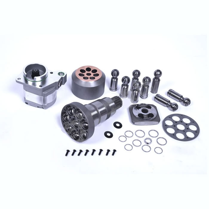
(1) Push the oil sealing bulkhead 9 together with the sealing ring on it into the spline grooved hole against the output end of the cylinder block, and lock the hole with the elastic retaining ring 8 to locate the shaft (see Figure 6-7) .
(2) Press the rear cover 6 with the sealing ring on the flange into the concave edge of the guide rail, and position the two with the positioning pin 12. After tapping and pressing firmly, the opening is placed upward.
(3) Put the steel ball 1 and the plunger 5 in groups into the plunger hole L of the cylinder block 2, and turn the cylinder block 2 slightly to make it enter the curved surface of the guide rail.
(4) Connect the front end cover 7 with the rotary oil seal embedded in the inner hole to the guide rail 3 and the rear cover 6 with screws, and turn the output shaft end (ie the cylinder block 2) while tightening the screws, so that there is no unilateral block in the rotation.
(5) When putting the spring 10 and the speed change valve 11 into the inner hole of the distribution shaft 4 for use as a variable motor, the screw plug at the end of the speed change valve (see Figure 6-14, item No. 3) must be screwed on; it is used as a fixed motor. , the screw plug should be removed.
(6) Install the distribution shaft 4 on the rear cover 6 with screws. When tightening the screws, tighten them diagonally and evenly in sequence. Rotate the output shaft 2 without unilateral blockage.
use and maintenance
(1) Instructions for use
Because the Hydraulic Motor works in the hydraulic transmission system, the reliability and life of the entire device are largely related to the selection, correct use and maintenance of various components in the Hydraulic System.
Hydraulic Motors, Hydraulic pumps and other hydraulic components are relatively precise and complex components. In order to make all components of the hydraulic transmission work normally, the following points must be paid attention to:
(1) Select a reasonable hydraulic transmission system;
(2) Use the working fluid that meets the structural requirements and operating conditions;
(3) Ensure oil filtration;
(4) Reliably prevent the hydraulic machine from being subjected to unacceptable loads;
(5) When the hydraulic system is thermally balanced, it should be ensured that the temperature of the working fluid is not greater than 60°C;
(6) Adopt the control mechanism, monitoring and protection instruments and auxiliary equipment that fully meet the operational requirements;
(7) Ensure the installation quality of the hydraulic system;
(8) Regular inspection, maintenance and overhaul of hydraulic transmission devices.
(2) Working oil
According to the statistical analysis of hydraulic equipment failures, more than 70,010 accidents are caused by serious pollution of working oil. Therefore, the basic requirements for working oil:
(1) The working liquid should be stable, that is, it can keep its properties unchanged or change little during operation and storage. The oil should have oxidation resistance when in contact with air; it should be stable under the action of mechanical force; it should not produce precipitates on the contact surface during storage and operation.
(2) It has suitable viscosity and good viscosity-temperature characteristics. The viscosity of the oil should not decrease significantly as the temperature rises.
(3) The working fluid should not interact with the materials (metal, plastic, rubber, etc.) of the components of the hydraulic system.
(4) The working liquid should have good thermal conductivity. When the hydraulic system is working, the working fluid should bring the heat from the higher temperature to the cooler place. This is one of the additional tasks that the working fluid should accomplish.
(5) The working fluid should have a high bulk modulus of elasticity. The higher the bulk modulus, the harder the liquid is to compress (meaning under pressure). The working accuracy of the hydraulic system is related to the elastic modulus of the liquid. In the presence of air bubbles in the working fluid, its elastic modulus decreases sharply.
(6) The working liquid should have little volatility. It is desirable for the working fluid to have a low saturated vapor pressure and a high boiling temperature. The working fluid should have little foaming, because a large amount of foam will cause the hydraulic system to not work properly.
(7) The working liquid is preferably non-flammable, and the use of flammable working liquid will increase the risk of fire.
(8) Economical and practical.
The user shall select the appropriate grade of oil according to the requirements of the manufacturer, and shall also set up the relevant oil filter device according to the provisions of the instruction manual to ensure the cleanliness of the hydraulic motor and the entire hydraulic system.
(3) Operation and maintenance
QJM series motors are the same as other low-speed and high-torque motors with inner curve, the following points should be paid attention to during operation and inspection:
(1) Before installing the hydraulic motor on the transmission, its casing must be filled with working fluid. If during inspection it is found that the housing is not filled with working fluid, the hydraulic motor must be disassembled and any traces of rust removed. When the hydraulic motor has been stored for a long time and the oil has not been changed, the old oil should be poured out and new working fluid should be poured during installation.
If the hydraulic motor uses clean hydraulic oil of the same grade as the working fluid of the hydraulic system during storage, the oil in the inner cavity of the hydraulic motor may not be replaced before installation.
(2) When installing the hydraulic motor, the process specified in the manual must be followed. Note that the thread length of the pipe joint connecting the motor drain hole is less than or equal to 10mm, and the diameter of the pipe joint is greater than or equal to 10mm. Special tools and equipment must be used to assemble and disassemble the hydraulic motor. It is absolutely forbidden to weld the connecting pipe to the hydraulic components, so as not to damage the precise matching moving surface of the hydraulic machine. When installing the pipeline, the necessary distance should be kept between the pipelines and components of the hydraulic transmission device, so as to observe, monitor and repair the hydraulic components and pipelines.
(3) It is not allowed to inspect and disassemble the components of the hydraulic transmission device under pressure.
(4) During installation, the hydraulic components, especially the dirt in the pipeline, should be removed. To this end, the workplace should be kept clean, and all inlets and outlets of the working fluid, the ends of pipes, the ports of hoses and hydraulic components, etc., should be closed with plugs and removed before installation.
(5) Before starting the hydraulic device, the following work must be done: unscrew the air plug to release the air in the hydraulic device and hydraulic pipeline; check whether the entire hydraulic system is installed correctly; check and adjust the components to prevent overload; check the working fluid level ; Turn on monitoring and measuring instruments (pressure gauges first); remove all irrelevant items and tools; disconnect machinery driven by hydraulic devices; notify the operator to start the hydraulic transmission; check the steering of the hydraulic motor.
(6) During the test run, first input a certain flow of working fluid, so that the speed of the hydraulic motor is equal to 20%-30% of the rated speed. Then, accelerate step by step until the test drive is carried out at the rated speed. In the case of no load and disconnection of the actuator, the pressure drop should generally not exceed 0.5 ~ lMPa.
During the trial operation of the hydraulic transmission device, the hydraulic motor is not allowed to have impact sound, the rotating shaft is unstable, and the working fluid leaks from the sealing parts such as screw plugs and end caps.
If the above faults are found, and in the case of high pressure during idle operation, the hydraulic transmission should be stopped immediately. The hydraulic transmission can only be restarted after the fault has been identified and eliminated.
After the no-load operation, connect the actuator to make the transmission test under the load (the load of the hydraulic transmission should be gradually increased reasonably). Under no circumstances should the pressure exceed the rated value. During the test, the operation of the hydraulic transmission device under various working conditions should be checked.
(7) When carrying out the system test, attention should be paid to measuring the leakage of the hydraulic motor, because the volume loss value characterizes the condition of the working parts of the hydraulic motor. If the leakage exceeds the range allowed by the instruction manual, the hydraulic motor should be removed and used after repair.
(8) During the operation, the height of the working fluid, the condition of the oil filter, and whether there is any leakage at the connection of the pipeline should be checked every shift. If a fault is found, it should be eliminated immediately. The operator should always pay attention to the indication of the measuring instrument, and do not allow the equipment to work under overload and temperatures higher than those specified in the instruction manual. The noise characteristics of the equipment during operation are very helpful for judging the failure of the hydraulic motor. According to the noise level and frequency spectrum of the hydraulic motor, it is possible to determine whether it is working properly even without special instrumentation.