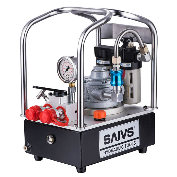
Hydraulic shock caused by sudden changes in the hydraulic oil velocity within a hydraulic motor
Hydraulic shock refers to the process of rapid fluctuation in liquid pressure
within a fluid channel when the flow passage is suddenly opened or closed in a Hydraulic System.
When hydraulic shock occurs, the instantaneous peak pressure in the liquid is often several times higher than the normal working pressure,
which not only damages the sealing devices, pipelines, and hydraulic components, but also causes vibration and noise,
and sometimes causes hydraulic components under pressure control to malfunction, leading to accidents.
")
I. Hydraulic shock caused by sudden changes in flow rate within a pipe
Consider a container with a constant liquid level and capable of maintaining a constant liquid pressure, shown in Figure 3.40. A pipeline is connected to the bottom of the container, and a valve is installed at the output end of the pipeline. The liquid in the pipeline flows out through valve B. If the valve is suddenly closed, the liquid immediately stops moving in the section near the valve. The kinetic energy of the liquid is instantaneously converted into potential energy, resulting in a shock pressure. Then, the liquid behind the front section stops in turn, sequentially transforming the kinetic energy into potential energy, forming a pressure shock wave in the pipeline, and propagating towards point A at a speed of c.
Assuming the cross-sectional area and length of the pipeline in Figure 3.40 are A and Z, respectively, the flow velocity of the liquid in the pipeline is V and the density is p. According to the law of conservation of energy, the kinetic energy of the liquid is converted into potential energy, i.e.
2lpAlv2=1/2Al/K‘△prmax
Therefore,
△prmax=ρ√K’/ρV=ρcv
where △prmax is the increase in pressure during hydraulic shock;
K’ is the equivalent volume modulus of the liquid taking into account the elasticity of the pipe wall;
c is the propagation speed of the pressure shock wave in the pipeline, c=√k’/ρ.
The propagation speed of the pressure shock wave in the hydraulic fluid in the pipeline can be calculated according to the following formula:
c=√K’/ρ=√K/ρ/√1+d/δK/E
where K is the volume modulus of the liquid;
d is the inner diameter of the pipe;
δ is the wall thickness of the pipe;
E is the elastic modulus of the pipe material.
The propagation speed of the pressure shock wave in the hydraulic fluid in the pipeline is generally in the range of 890-1420m/s. If the valve is not completely closed, but partially closed, causing the flow rate of the liquid in the pipeline to decrease from V to V', the increase in pressure can be calculated by replacing V with (V-V') in Formula (3-69), i.e.
△pr=pc(v-v’)=pc△v
Generally speaking, hydraulic shock caused by closing the flow passage is divided into two types according to the duration of valve closure:
If the valve closure time t<tc=2l/c, it is called direct hydraulic shock;
If the valve closure time t>tc=2l/c, it is called indirect hydraulic shock.
The increase in pressure in the latter case is smaller than that in the former case and can be approximately calculated by the following formula:
Ap,≈ pcv
(also known as complete shock)
(also known as incomplete shock)
In this way, the maximum pressure in the pipeline when hydraulic shock occurs can be calculated by knowing the increase in pressure Ap, i.e.
Pmax=p+Ap
where p is the normal working pressure.
Table 3-7 summarizes the increase in pressure during hydraulic shock under various valve closure conditions.
Table 3-7: Increase in pressure during hydraulic shock under various valve closure conditions
Valve closure conditions
Increase in pressure during hydraulic shock (△p)
Instantaneous closure of flow passage (t≤t0) (V'=0)
Ap=pcv
Partial closure of flow passage (t≤t0) (V'≠0)
Ap=pc(V-V')
Gradual closure of flow passage (t>t0) (V'=0)
Ap≥pc(1-V'/V)
Gradual closure of flow passage (t>t0) (V'≠0)
Ap≥pc(1-V'/V)
Regardless of the closure condition, by knowing the increase in pressure during hydraulic shock Ap, the maximum pressure in the pipeline when hydraulic shock occurs can be calculated, i.e.
Pmax=p+Ap
where p is the normal working pressure.
The pressure drop in a straight pipe with an open valve at the end is shown in Table 3-8.
II. Hydraulic shock caused by motion components braking
As shown in Figure 3.41, the piston drives the load m to move to the left at a speed of V, and the total mass of the piston and load is ∑m. When the outlet channel is suddenly closed, the liquid is sealed in the left chamber due to the inertia of the moving components, causing a sudden rise in liquid pressure. The moving component is then braked due to the resistance generated by the liquid pressure in the left chamber.
Assuming the deceleration time of the moving components during braking is Af, the decrease in speed is Av; according to the law of momentum, the hydraulic shock pressure in the left chamber can be approximately calculated as follows:
ApAAt=∑mAv
Therefore,
where ∑m is the total mass of the moving component (including the piston and load);
A is the effective working area of the Hydraulic Cylinder;
At is the braking time of the moving component;
Av is the change in speed of the moving component, Av=V-V';
V is the speed of the moving component before braking;
V' is the speed of the moving component after At.
The above calculation neglects damping, leakage and other factors, and its value is larger than the actual value, making it somewhat conservative.
To reduce the hydraulic shock caused by the factors influencing the hydraulic shock pressure Ap in the above formulas, the following measures can be taken:
1) appropriately increase the pipe diameter to limit the flow rate of the pipeline, which is generally controlled within 4.5m/s in hydraulic systems, so that the maximum increase in pressure Ap does not exceed 5MPa for safety.
2) properly design the valve or set the braking device to make the speed of the moving component change more evenly.
3) prolong the valve closure and the braking reversal time, and use a reversing valve with adjustable reversal time.
4) make the pipeline as short as possible to reduce the propagation time of the pressure shock wave and change direct shock into indirect shock.
5) use a rubber hose or a accumulator to absorb the shock pressure in the parts prone to hydraulic shock; safety valves can also be installed in these parts to limit the increase in pressure.